ProtocolIO-Link®
Dimensions (W x L x H)50.1 mm x 107.3 mm x 57.5 mm
Grid dimension50.1 mm
Type of mountingScrew-clamped
Product weight90 g
Mounting positionoptional
Ambient temperature-20 °C ... 50 °C
Note on ambient temperatureObserve ambient temperature derating according to IEC 61131-2:2017
Storage temperature-20 °C ... 70 °C
Relative air humidity5 - 95% Non-condensing
Nominal altitude of use<= 2000 m ASL (> 79.5 kPa)
Max. installation height3500 m
Note on max. installation heightObserve ambient temperature derating according to IEC 61131-2:2017
Corrosion resistance class CRC1 - Low corrosion stress
Vibration resistanceTransport application test with severity level 2 to FN 942017-4 and EN 60068-2-6
Note on vibration resistanceSG1 on H-rail SG2 on direct mounting Transport application test with severity class 1 to FN 942017-4 and EN 60068-2-6
Shock resistanceShock test with severity level 2 to FN 942017-5 and EN 60068-2-27
Note on shock resistance30 g/11 ms to EN 60068-2-27 SG1 on H-rail SG2 on direct mounting Shock test with severity level 1 to FN 942017-5 and EN 60068-2-27
Protection classIII
Pollution degree2
Overvoltage categoryII
Max. cable length20 m with IO-Link® operation
LABS (PWIS) conformityVDMA24364-B2-L
Fire test materialUL94 V-0 (housing)
Note on materialsRoHS-compliant Free of halogen Free of phosphoric acid ester
Material coverPBT-reinforced
Material screwsNickel-plated steel
Material o-ringFPM
Diagnostics via LEDDiagnostics per channel Diagnostics per module Load power supply Status per channel Status per module
Diagnostics per internal communicationIO-Link® event Short circuit/overload in sensor supply Electronics/sensors overvoltage Load overvoltage Electronics/sensors undervoltage Load undervoltage
Max. address volume, inputs33 Byte
Max. address volume, outputs33 Byte
Module parametersConfiguration of voltage monitoring load supply PL
Channel parametersActivation diagnostics for IO-Link® device lost Port mode Target deviceID Target vendorID Target cycle time
Internal cycle time< 1 ms
Configuration supportIODD file
Communication interface, protocolAP
Note regarding operating voltageSELV/PELV fixed power supplies required Note voltage drop
Note on nominal operating voltage DCProtected Extra-Low-Voltage to IEC 60204-1
Nominal operating voltage DC of load24 V
Permissible voltage fluctuation of load± 25 %
Nominal DC operating voltage, electronics/sensors24 V
Permissible voltage fluctuations for electronics/sensors± 25%
Intrinsic current consumption at nominal operating voltage for electronics/sensorsTypically 40 mA
Intrinsic current consumption at nominal operating voltage loadTypically 4 mA
Power failure bridging10 ms
Potential separation between the supply voltages electronics/sensor technology and load/valvesYes
Reverse polarity protectionyes
Fuse protection of inputs (short circuit)Internal electronic fuse per module
Max. residual current of inputs per module2 A
Behaviour after end of overload of the outputsNo automatic return
Max. residual current outputs per module4 A
Electrical isolation of outputs between channel - internal communicationyes
Max. power supply per channel2.1 A (50 W lamp load), per channel pair
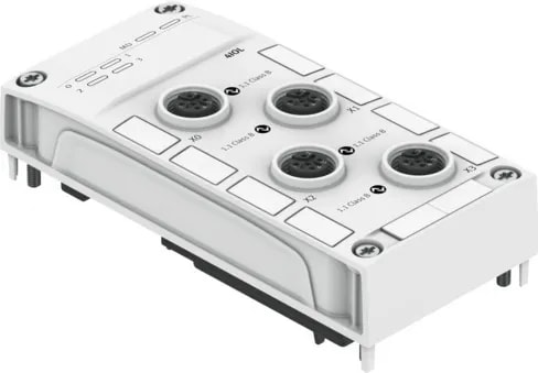
Electrical connection for IO-Link, connection type4 x socket
Electrical connection for IO-Link, connection technologyM12x1, A-coded to EN 61076-2-101
Electrical connection for IO-Link, number of pins/wires5
Electrical connection for IO-Link, connection pattern00995384
IO-Link, communicationC/Q green LED
IO-Link, Number of ports4
IO-Link, Port classB
IO-Link, Protocol versionMaster V 1.1
IO-Link, communication modeDI, COM1. COM2. COM3. Configurable via software
IO-Link, Process data length OUTCan be parameterised, 8-128 bytes
IO-Link, Process data length INCan be parameterised, 12-132 bytes
IO-Link, Min. cycle timeDependent on minimum supported cycle time of the connected IO-Link® device
.webp)