Dimensions (W x L x H)(incl. interlinking block) 50.1 mm x 107.3 mm x 57.5 mm
Grid dimension50.1 mm
Type of mountingScrew-clamped
Product weight145 g
Mounting positionoptional
Ambient temperature-20 °C ... 50 °C
Note on ambient temperatureObserve derating according to user documentation Observe ambient temperature derating according to IEC 61131-2:2017
Storage temperature-20 °C ... 70 °C
Relative air humidity5 - 95% Non-condensing
Nominal altitude of use<= 2000 m ASL (> 79.5 kPa)
Max. installation height3500 m
Note on max. installation height> 2000 m ASL (< 79.5 kPa) Observe derating according to user documentation Observe ambient temperature derating according to IEC 61131-2:2017
Corrosion resistance class CRC1 - Low corrosion stress
Vibration resistanceTransport application test with severity level 2 to FN 942017-4 and EN 60068-2-6
Note on vibration resistanceSG1 on H-rail SG2 on direct mounting Transport application test with severity class 1 to FN 942017-4 and EN 60068-2-6
Shock resistanceShock test with severity level 2 to FN 942017-5 and EN 60068-2-27
Note on shock resistance30 g/11 ms to EN 60068-2-27 SG1 on H-rail SG2 on direct mounting Shock test with severity level 1 to FN 942017-5 and EN 60068-2-27
Protection classIII
Pollution degree2
Overvoltage categoryII
Max. cable length200 m outputs 200 m inputs
LABS (PWIS) conformityVDMA24364-B2-L
Fire test materialUL94 V-0 (housing)
Note on materialsRoHS-compliant Free of halogen Free of phosphoric acid ester
Material coverPBT-reinforced
Material screwsNickel-plated steel
Material threaded sleeveHigh-alloy stainless steel
Material o-ringFPM
Diagnostics via LED(Outputs) Diagnostics per channel Power supply load (outputs) (Inputs-Outputs) Diagnostics per module (Inputs-Outputs) Status per channel
Max. address volume, inputs5 Byte
Max. address volume, outputs6 Byte
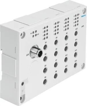
Number of outputs3
Module parametersFDevice destination address FDevice source address Configuration of voltage monitoring load supply PL
Communication interface, protocolAP
Note regarding operating voltageSELV/PELV fixed power supplies required Note voltage drop
Note on nominal operating voltage DCProtected Extra-Low-Voltage to IEC 60204-1
Nominal operating voltage DC of load24 V
Permissible voltage fluctuation of load± 25 %
Nominal DC operating voltage, electronics/sensors24 V
Permissible voltage fluctuations for electronics/sensors± 25%
Intrinsic current consumption at nominal operating voltage for electronics/sensorsTypically 60 mA
Intrinsic current consumption at nominal operating voltage loadTypically 15 mA
Power failure bridging10 ms
Potential separation between the supply voltages electronics/sensor technology and load/valvesYes
Reverse polarity protectionyes
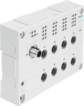
Electrical connection input, functionDigital input
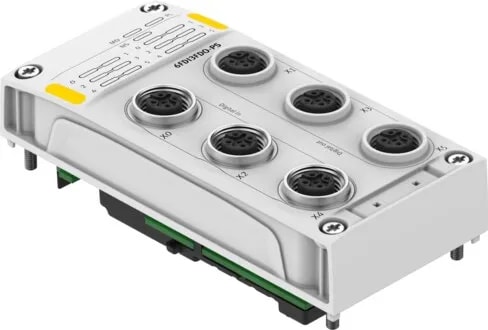
Electrical connection input, connection type3 x socket
Electrical connection input, connector systemM12x1, A-coded to EN 61076-2-101
Electrical connection input, number of connections/cores5
Electrical connection input, connection pattern00995384
Number of inputs6
Characteristic for inputsTo IEC 61131-2, type 3
Switching levelSignal 0: <= 5 V Signal 1: >= 11 V
Switching logic for inputsPNP (positive switching) 2-wire sensors to IEC 61131-2 3-wire sensors to IEC 61131-2
Input debounce time2.5 ms
Behaviour after end of overload of the sensor supplyAutomatic return
Fuse protection of inputs (short circuit)Internal electronic fuse per channel
Max. residual current of inputs per module1.44 A
Electrical isolation of inputs between channelsno
Electrical isolation of inputs between channel – internal communicationNo
Electrical connection output, functionDigital output
Electrical connection output, connection type3 x socket
Electrical connection output, connector systemM12x1, A-coded to EN 61076-2-101
Electrical connection output, number of connections/cores5
Electrical connection output, connection pattern00995384
Characteristic for outputsBased on IEC1131-T2 To IEC 61131-2, type 2
Switching logic for outputsPNP (positive switching)
Fuse protection of outputs (short circuit)Internal electronic fuse per channel
Behaviour after end of overload of the outputsNo automatic return
Output delay with ohmic loadSignal change 0->1: < 100 µs Signal change 1->0: < 100 µs
Max. residual current outputs per module4.5 A
Electrical isolation of outputs between channelsno
Electrical isolation of outputs between channel - internal communicationyes
Max. power supply per channel1.5 A
.webp)